| Illus No: | Part No: | Description: | Qty: |
|---|---|---|---|
| S1: | SB:1 | Base - Engine | 1 |
| S2: | SB:2 | Base - Gasket | 1 |
| S3: | SB:3 |
Base - Oil Trough | 1 |
| S4: | SB:4 | Base - Oil Trough - Fixing Bolt | 2 |
| S7: | SB:7 | Base - Oil - Drain Plug | 1 |
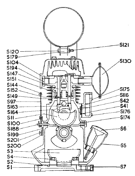
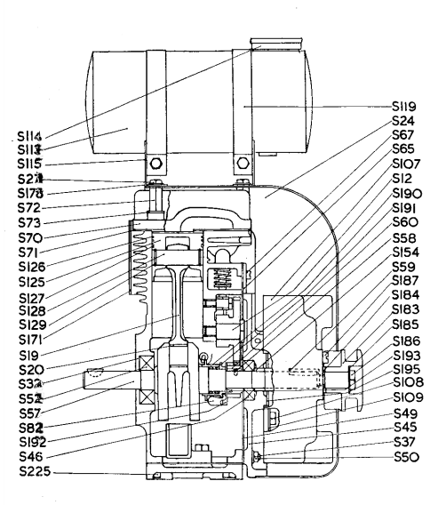
I'm hoping this will be a great resource for anyone who decides to restore a J.A.P. Model 2A.
It is the comlpete breakdown of the little JAP Model 2A - as the title suggests - part by part.
You can scroll through the entire page and check out everything.
Or if you have a particular part in mind - just check out the Parts Diagrams and find the part you want - then click on its List Entry, and you'll be taken to the part you requested.
For each part you'll be able to see before and after photos of my particular engine and parts - as well as some general comments on any particular difficulties I had, how I got it apart, together, where I found spare parts etc.
|
|
|
 |
|
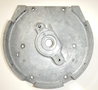
| Base - Engine | |
|---|---|
| Part No: SB:1 | |
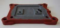 |
The base on which the engine sits - this is essentially the bottom of the sump. An alloy plate that serves as both the engine base and the bottom of the sump. Internally, the oil trough attaches to this plate via a couple of bolts, you will see the threaded holes for these bolts towards the centre of the base. In all there are 10 threaded holes:
|
| Date Removed: | 28 March 2015 |
| Condition: |
Not too bad - it will easily still serve its purpose. A reasonable amount of corrosion on the bottom face, but nothing too bad - in any case it won't be seen once the engine is fixed to it's trolley. |
| Comments: |
Once again - the main attack was to clean it up with degreaser, followed by soap and water and a plastic scrubbing brush. Then a bit of a clean with the rotary tool and a coat of Red Oxide primer ready for the top coat. Of course the outside took a lot more cleaning than the inside!! Its interesting to not the difference between the internal and external faces. The internal faces are nice - really well preserved - no corrosion, no pitting etc - of course on the outside - lots of pitting, corrosion, a little bit of physical damage. Of course that's exactly what you would expect with all the oil on the inside, and the rain and weather on the outside!! But its interesting to see just how nice the oil keeps the metal. Unfortunately there are no "before" photos for this piece - I pulled it all apart and began work before I decided I was going to create this web site. |
| Photos | |||||
|---|---|---|---|---|---|
| Before Restoration | |||||
| Front | Right | Back | Left | Top | Bottom |
| After Restoration | |||||
| Front | Right | Back | Left | Top | Bottom |
| Engine Base Gasket | |
|---|---|
| Part No: SB:2 | |
 |
Gasket that sits between the Engine Base and the Crankcase housing |
| Date Removed: | 28 March 2015 |
| Condition: |
Destroyed |
| Comments: |
No surprise here - the gasket was destroyed when I disassembled the engine. Bought a new one - they are still readily available - and quite reasonably priced - I bought an entire Gasket Kit for the J.A.P. 2A, including the Aluminium Head Gasket for £11.00 - from George at: villiersparts.co.uk |
| Photos | |||||
|---|---|---|---|---|---|
| Before Restoration | |||||
| Front | Right | Back | Left | Top | Bottom |
| After Restoration | |||||
| Front | Right | Back | Left | Top | Bottom |
| Oil Trough | |
|---|---|
| Part No: SB:3 | |
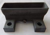 |
This sits inside the sump, bolted to the engine/sump base by parts SB4 - Oil Trough - Fixing Bolt. |
| Date Removed: | 28 March 2015 |
| Condition: |
As new. |
| Comments: |
This part lives a charmed life - it sits inside the sump - doesn't move - and is bathed in oil the whole time. So as you might imagine, its in perfect condition. Though there is one part, and I don't really know what its for. At the bottom of the trough itself, there is a single screw, which doesn't really seem to serve much purpose. It looks like it could be a drain plug, but what on earth would you want/need a drain plug at that point for?? |
| Photos | |||||
|---|---|---|---|---|---|
| Before Restoration | |||||
| Front | Right | Back | Left | Top | Bottom |
| After Restoration | |||||
| Front | Right | Back | Left | Top | Bottom |
| Oil Trough - Fixing Bolt | |
|---|---|
| Part No: SB:4 | |
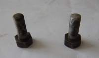 |
A couple of bolts that hold the Oil Trough to the Engine/Sump Base. |
| Date Removed: | 28 March 2015 |
| Condition: |
Reasonbly good - just 70 years of oil and crud and gunk to be cleaned off. |
| Comments: |
These are in great condition because they live in the sump - surrounded by oil and living the good life. No need to do anything to these other than a basic clean - they were in perfect condition when they came out. They came out easily. No need for special tools - just a 1/4 Whitworth socket - if you don't have Whitworth then 9/16th inch or a 14mm sockets are close - - the 14mm seems closer than the 9/16th - but try and use the right size for everything. |
| Photos | |||||
|---|---|---|---|---|---|
| Before Restoration | |||||
| Front | Right | Back | Left | Top | Bottom |
| After Restoration | |||||
| Front | Right | Back | Left | Top | Bottom |
| Oil Drain Nut | |
|---|---|
| Part No: SB:7 | |
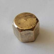 |
Nut that fits over the drain hole in the sump. |
| Date Removed: | 28 March 2015 |
| Condition: |
Reasonbly good - just 70 years of oil and crud and gunk to be cleaned off. |
| Comments: |
Brass nut that fits over the drain hole on the right hand side of the Engine/Sump Base. > It looks like it's had a lot of spanners on it over the years - lots of little nicks and bumps etc - but that's good news really - it tells me the engine has had lots and lots of oil changes over the years - and I don't know about you - but I think if the only maintenance you ever do to an engine is change the oil every couple of mponths - it will always be good to you And the proof is in the pudding, so to speak - when you examine the insides of this engine, so you see the benefits of regular oil changes. I suspect a lot of the linear gouges you can see were my fault - I cleaned this with a wire brush on my rotary tool - and I think the wire brush was harder than the Brass Nut, so it gouged out those lines you can see. I have now ordered a bunch of little brass wire wheels so it won't happen again. |
| Photos | |||||
|---|---|---|---|---|---|
| Before Restoration | |||||
| Front | Right | Back | Left | Top | Bottom |
| After Restoration | |||||
| Front | Right | Back | Left | Top | Bottom |
| Cowl | |
|---|---|
| Part No: SB:24 | |
 |
Cowling that covers the engine - also works to direct airflow generated by the fins on the flywheel back through the cooling fins to assist with engine cooling. |
| Date Removed: | 28 March 2015 |
| Condition: |
Reasonable - a bit of surface rust both nothing too serious - a few dings and dents but again, nothing to tragic. |
| Comments: |
Cleaning in progress...... The cowl has an instruction label attached to its left face (or right face if you are looking at the engine from the pull start side) and an Identification Plate attached to its left face. You can get a copy of the Instructions label here at the Resources section. |
| Photos | |||||
|---|---|---|---|---|---|
| Before Restoration | |||||
| Front | Right | Back | Left | Top | Bottom |
| After Restoration | |||||
| Front | Right | Back | Left | Top | |
| Crankcase and Barrel Assembly | |
|---|---|
| Part No: SB:32 | |
 |
This is the crankcase and barrel/cylinder assembly. It's all one single block of cast iron. Solid as a rock. |
| Date Removed: | 28 March 2015 |
| Condition: |
This was in pretty good shape when I got it - no rust - just 50 years worth of dirt, dust, grease and grime. |
| Comments: |
This is pretty much the last bit we are left with when doing the disassembly. I had all sorts of trouble getting to this stage, as some previous owner had installed a little pulley that I had very little idea, and even less tools to remnove. And of course I had to remove the pulley to get the crankshaft out of the engine. Fortunately I was able to get some help off Grant, one of the local engine restorers, and once he set his mind to it, the pulley was off within an hour. Once the pulley was off, the valves, crankshaft and governor weights were taken out, leaving me with this single block. Everything was then given a good clean - degreaser, scrubbing and hosing - followed by a couple of dips into Grant's industrial Ultrasounic cleaner. There was virtually no rust at all on the engine block - and when it came out of the ultrasonic cleaner, it was looking pretty good. Then a good clean with Grease and Wax Remover, and a coat of Red Oxide Primer - and it's ready for the top coat. |
| Photos | |||||
|---|---|---|---|---|---|
| Before Restoration | |||||
| Front | Right | Back | Left | Top | Bottom |
| After Restoration | |||||
| Front | Right | Back | Left | Top | Bottom |
| Bearing Plate | |
|---|---|
| Part No: SB:45 | |
 |
Aluminium Plate the bolts onto the crankcase - it holds one of the crank bearings - hence its name. |
| Date Removed: | 28 March 2015 |
| Condition: |
Good - just a bit dirty |
| Comments: |
In pretty good nick - as you'd expect I guess. There are a lot of bits and pieces around this thing to protect it - so it doesn't get a hard life - and the inside faces into the crank case so its always getting oiled. To clean it up I just soaked it in degreaser, gave it a scrub with a plastic brush and scotch brite and then attacked it with my Karcher. I was gonna get all silly and polish it, but whats the point, you can't see it anyway. |
| Photos | |||||
|---|---|---|---|---|---|
| Before Restoration | |||||
| Front | Right | Back | Left | Top | Bottom |
| After Restoration | |||||
| Front | Right | Back | Left | Top | Bottom |
| Cylinder Head | |
|---|---|
| Part No: SB:70 | |
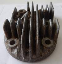 |
Cylinder Head - I'm guessing you probably don't need an explanation of what that is. |
| Date Removed: | 28 March 2015 |
| Condition: |
Good - but dirty - as you'd expect from a 70 year old engine. |
| Comments: |
As you can see from the photos below - I had started to clean this up prior to taking the "Before" photos. I just wanted to see what it would come up like. The process for cleaning thios was - Degreaser - Degreaser - More Degreaser - Wash in soapy water and get it as clean as I possibly could. Then, start of with coarse sandpaper - which for me was about 360 grit Wet & Dry - sand sand and sand. Then 400 grit Wet & Dry - sand, sand and sand. Then 600 grit Wet & Dry - sand, sand and sand. Then 800 grit Wet & Dry - sand, sand and sand. Then 1000 grit Wet & Dry - sand, sand and sand. Then 1200 grit Wet & Dry - sand, sand and sand - and by this time it should be starting to look really good. Then out with the rotary tool and the AutoSol (Metal Polish) and shine it up with that - it will come up like a mirror - of course if you don't want it to have a mirror shine you need to go this far. As for the combusion chamber and the carbon - well - how does one do that - it seems like someone had had the head off and tried to decarbon it with a screwdriver before I got at it. I'm not sure how good an indea that is - but before I start criticizing - I should probably let you know that I don't really know of anything better - some things I've read are Diesel, |
| Photos | |||||
|---|---|---|---|---|---|
| Before Restoration | |||||
| Front | Right | Back | Left | Top | Bottom |
| After Restoration | |||||
| Front | Right | Back | Left | Top | Bottom |
| Cylinder Head - Gasket | |
|---|---|
| Part No: SB:71 | |
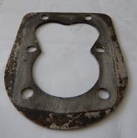 |
Cylinder Head - Gasket. |
| Date Removed: | 28 March 2015 |
| Condition: |
Good |
| Comments: |
I have a new head gasket - I bought it grom George at villiersparts.co.uk but I thought I'd try and see how well I can restore this one. After all, my next project is a J.A.P. MNodel 2S, so if I can restore this gasket to a really good, useable condition, I can use it here, and use my nice shiney new one on the 2S. |
| Photos | |||||
|---|---|---|---|---|---|
| Before Restoration | |||||
| Front | Right | Back | Left | Top | Bottom |
| After Restoration | |||||
| Front | Right | Back | Left | Top | Bottom |
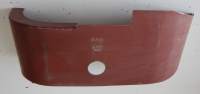
| Fuel Tank | |
|---|---|
| Part No: SB:113 | |
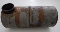 |
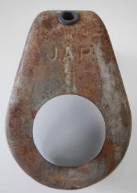
Fuel Tank - sometimes you see these round, sometimes an oval shape - - I don't really know how that works - I've seen both 2As and 2Ss with both round and oval tanks, so I don't think it is a feature of the model. But then again - the 2S is the industrial model, and is designed for longer, harder running, so it makes sense that it might have the larger, oval shaped tank. I don't really know. |
| Date Removed: | 28 March 2015 |
| Condition: |
Basically sound - minimal internal rust - a few bumps and scrapes on the outside - but nothing too dramatic - except for the stupid Swastika some previous owner had drawn on it!! |
| Comments: |
This is a classic example of painting being all about the preparation. It hasn't come up nearly as nice as the small baffle section - SB171 - and that's because I don't put nearly as much preparation into it. I gave it a pretty good degrease and clean, attacked it with a stiff wire brush on my angle grinder, and then a reasonable sanding, but that was about it. I put on a Red Oxide primer, and already I could see a few imperfections in the finish - so I gave them a half hearted sanding and then more primer. It looked reasonable so then I went on with the Dupli-Colour Polaris Blue Top Coat. Of course once the glossy top coat went on, every little dent, bump and imperfection showed up perfectly. By that time I wasn't really prepared to strip it all back and start again (which is really what I should have done) so I just charged on with a few more coats, sanding between each to get the worst of the imperfections out - and then a couple of coats of Top Coat Clear - and this is how it turned out. Not too bad I guess - but it could have been a lot better - at least the Swastika is gone :) |
| Photos | |||||
|---|---|---|---|---|---|
| Before Restoration | |||||
| Front | Right | Back | Left | Top | Bottom |
| After Restoration | |||||
| Front | Right | Back | Left | Top | Bottom |
| Baffle | |
|---|---|
| Part No: SB:171 | |
 |
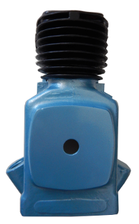
Smaller section of cowling that wraps around the cooling fins to helps direct cooling air through the cooling fins. |
| Date Removed: | 28 March 2015 |
| Condition: |
Missing!! |
| Comments: |
This bit was missing when I bought the engine. I thought there was bugger all chance of me finding one for sale - but much to my surprise, a quick eMail to George at VilliersParts.co.uk and I had a brand new one winging its way all the way from the UK to Australia.> When it arrived it had already been painted with Red Oxide so it was in great condition - I nte there were two different stampings on it, 1937 and 1960- not sure what they mean though. So there wasn't a great deal I had to do to it - I just gave it a light sanding, a really good clean with Wax and Grease remover and then gave it a souple of coats of my own Red Oxide - the same one that I've done the rest of the engine with. I'm a little concerned about that - the Red Oxide I am using doesn't claim to be heat proof - so I'm not sure how its going to go once the engine fires up. Anyway - a couple of coats of Red Oxide - a light sanding and then the top coat. It has come up really quite well :) A couple of coats of Dupli-Colour Polaris Blue and it came up a treat. This as about as close as I could come to what I believe was the original J.A.P. colour. Then finally, a couple of coats of Clear Top Coat and its done - I must admit - I'm pretty pleased with the way this has come up. |
| Photos | |||||
|---|---|---|---|---|---|
| Before Restoration | |||||
| Front | Right | Back | Left | Top | Bottom |
| After Restoration | |||||
| Front | Right | Back | Left | Top | Bottom |