1949 J.A.P. Model 2A Restoration
Preparation
As you may already know - work has forced me to live in a small one bedroom flat with no workshop or garage for at least a year.
So to feed my restoration habit - I've been forced to downsize what I restore - so I thought a small air cooled Stationary Engine would fit the bill perfectly.
First things first - I need an engine to restore - as usual - eBay was an obvious option. I wanted something a bit different to an old Briggs & Stratton - not that there's anything wrong with the trusty old Briggs - but I wanted something a little different. Went on to eBay and started watching what was coming up - after a week or two, I saw a couple of J.A.P.s appear. Hmmmm - I like British machinery, so my interest was piqued.The ad just listed "2 Small JAP Engines - Not working"
There were lots of other small engines around, but I have a J.A.P. Model 6 (what a beast!!) at home in Sydney waiting to be done - so I thought it would be cool to get another J.A.P. so the Model 6 wouldn't feel lonely.
I should add at this point that this is the very first Stationary Engine I have had a go at restoring - I've got a few old Victas 18 Lawn Mowers partially restored in Sydney, but this is the first actual Stationary Engine - I've got a lot in storage waiting to get done, but this is the first one I've actually done.
So watching eBay - and as luck would have it a single listing with TWO J.A.P.s came up. To cut a long story short - I bought them at auction for $102.50 - which is probably more than I should have paid, but hey, they'll keep me amused for a year.
Shipped them up to Port Douglas, unwrapped them - and what did have??
The eBay listing only stated "2 small JAP Engines" - so I didn't know what was arriving. I was quite pleased to see that they were twins!! A J.A.P. Model 2A and a J.A.P. Model 2S.
The first thing I always do when I get a new project is research!!
What is a J.A.P. 2A and what is a J.A.P. 2S?
They were obviously very similar to look at - but other than that I had no idea. Turns out they are essentially the same engine - both air cooled, 98cc single cylinderengines - with the 2A being the run of the mill engine and the 2S being the heavy duty, or Industrial version. The 2S has a bigger fuel tank, bigger sump with more oil capacity, a better govenor arrangement, all with the goal of allowing it to run longer and harder than the 2S.
So I was pretty pleased with my "twins". I like the idea of having them restored and displayed together.
After much procrastination - I decided to do the 2A first - I did consider doing them both at the same time - so I could do two heads, two sumps, two, pistons etc, etc at a time, but once again, the lack of room forced me into a corner.
Here are some of the resources I used to learn a bit about the J.A.P. Model 2 Engines
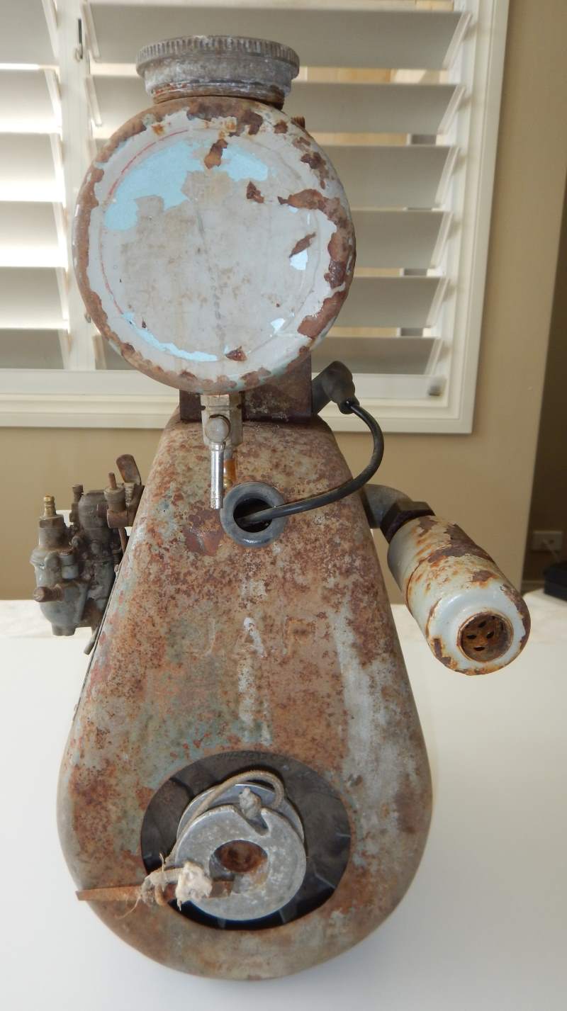
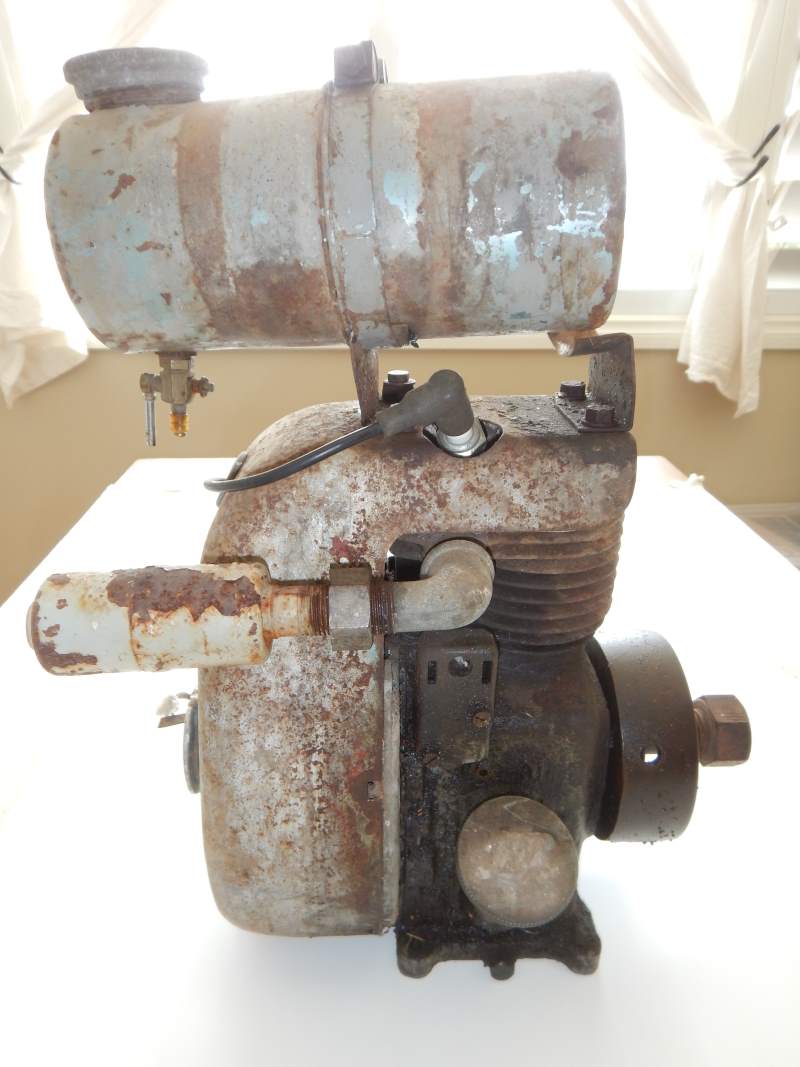
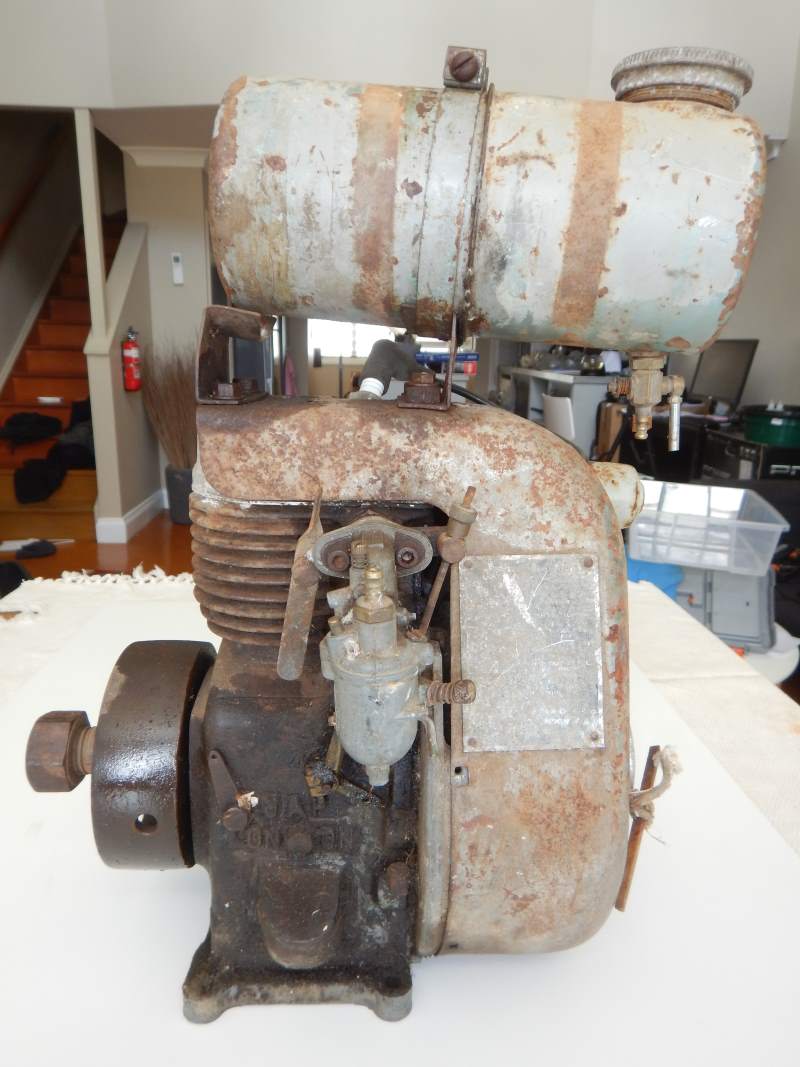
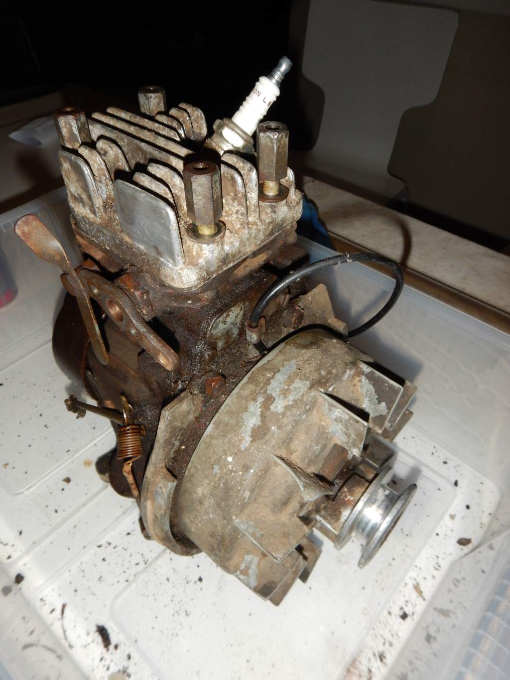
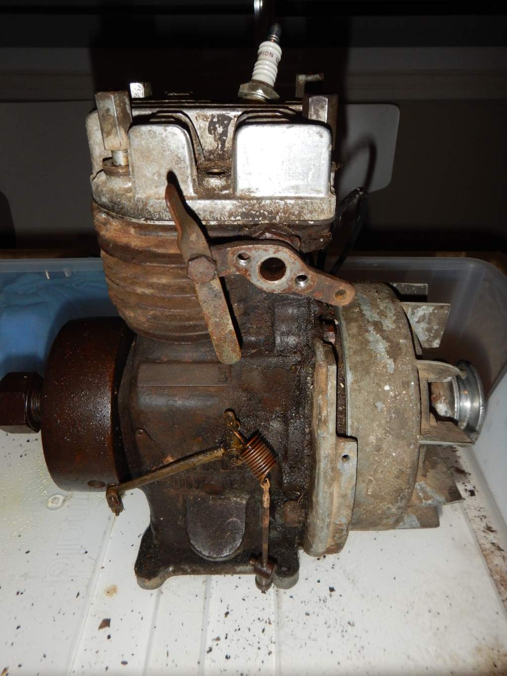
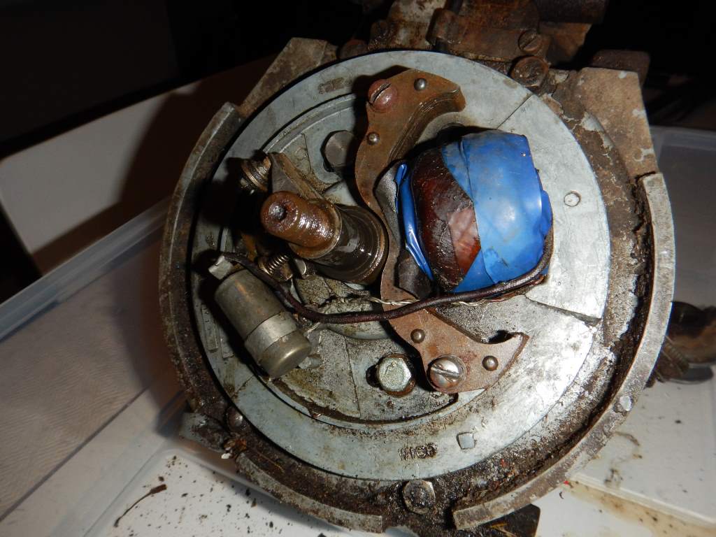
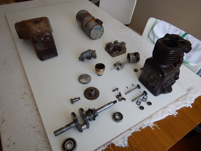
Here are a couple of pictures of the 2A when I first received it.
21 March 2015
Let the cleaning begin!!
The 2A wasn't in too bad a condition - but I usually start with a good clean. If only because I asm doing this entire restoration on my dining room table, so I need to be as clean as I possibly can.
So downstairs into the car park - Karcher at the ready - BLAST!!
Really my goal was just to get all the loose and caked on dirt/grease/gunk/mud/oil/etc off it so it didn't all fall off in my dining room.
It cleaned up OK - but I still went out and bought myself one of those 40 litre plastic storage tubs so I could sit the entire engine in it while it was on the table. It is only about 18 inches high - and weighs 14kg fully loaded so it's a nice small engine that can be worked on easily while inside the storage tub - perfect for what I want.
Allowed my self to have a bit of a play - checked the spark - none. Oh dear.
As I usually do - I got carried away with the excitement of a new project and immediately started pulling the thing apart - I always swear I'll njever do it again, but I always do - but at least now-a-days I take a lot of photos before I do - both while it's in tact, and as the disassembly progresses - but the further I go the less I take, but at least I'm better than I used to be.
At this stage I never had a copy of the manual - so I was kinda flying blind, but hey - what could go wrong?!?!!? :)
Off with the fuel tank (mental note - one tank holding strap is missing. Interesting (is that the right word??) find - dunno who has had this in the past - but I note there is a hand drawn Black Swastika on the side of the fuel tank!! Don't know what that's all about - certainly nothing official or anything - it was hand drawn in black texta pen, so probably a kid - it was done a looooong time ago and a lot of it has just worn off now - or was it rubbed off by someone who didn't like the iode of having it on their engine. You can just see its remnants in the photos above.
Off with the tank supports and cowl - carby and govenor - after LOTS of photos - off with the exhaust.
I was starting to realise that somebody else had had the engine apart at some stage. By this point I have usually broken a whole heap of things - snapped off rusted nutes and bolts, stripped Phillips Head screws - you know the story - but on this engine everything has come apart quite easily. I tried to convince myself that it was because I was smart enough to flood everything with penetrating oil, and patient enough to give it time to work - butg the reality was dawning on me that it had been apart before.
And with that realisation I had run out of time for the week-end so the engine was left partially disassembled, awaiting next week-end.
28 March 2015
Got stuck in today - got the fly wheel off:
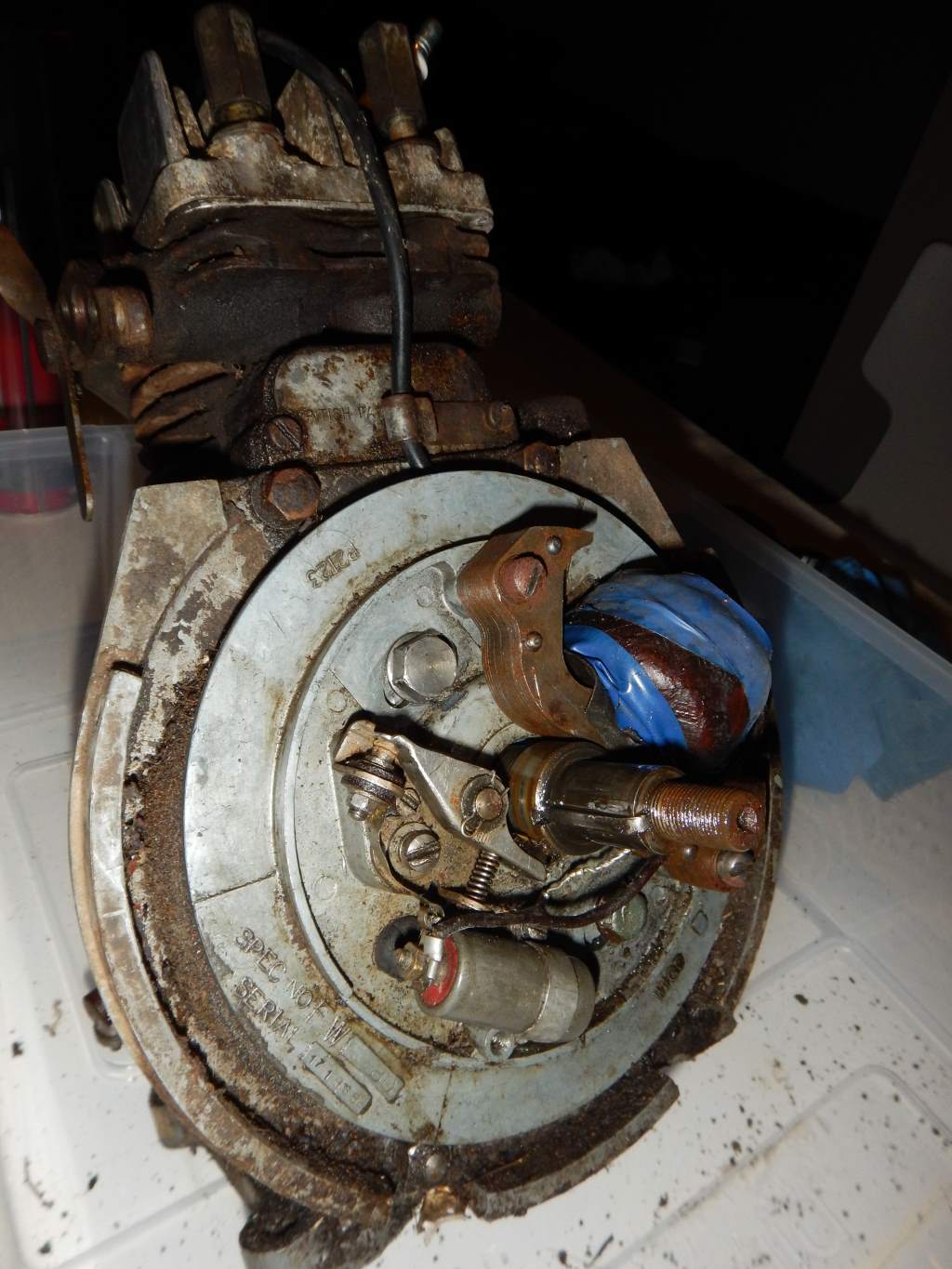
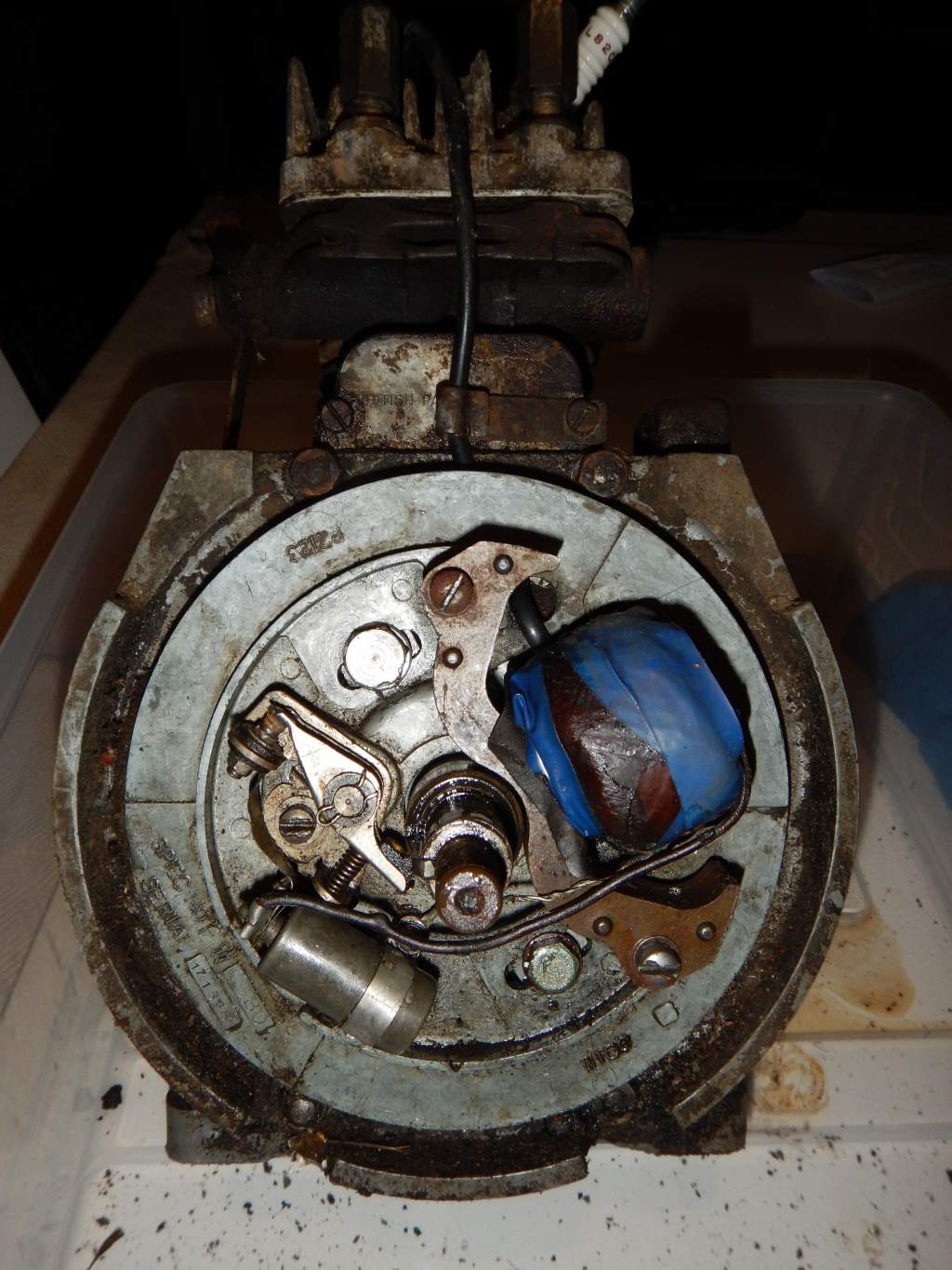
Got the magneto and the magneto backing plate off:
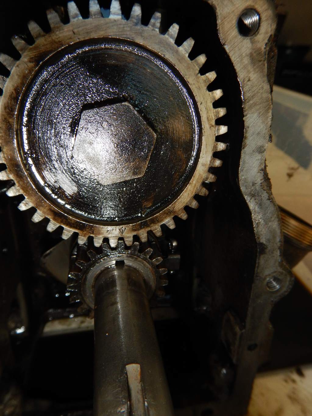
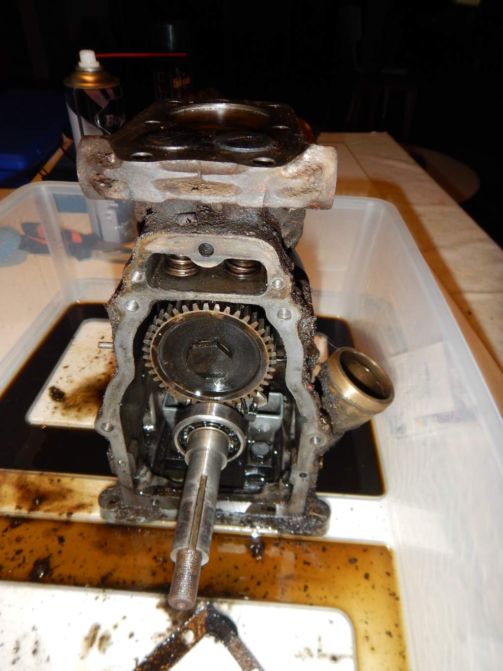
Note the timing marks on the gears (I've got a manual now) - the arrow you can see at 6 o'clock on the large gear - and there is a corresponding one on the smaller gear as well - its much more obvious after the gears were cleaned.
11 April 2015
It was round about this time that I discovered "The Mystery Part".
There sitting innocently in the bottom of the work box was this part I didn't recognise - and didn't remember taking off. I had no idea what it was or where it had come from.
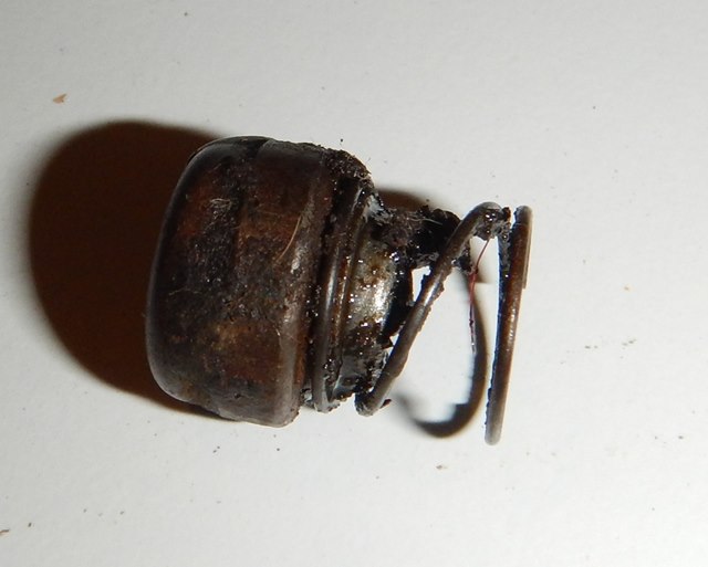
So to "Phone-a-Friend" - The Forums had a number of good suggestions - but none cracked the secret. It was obviously some kind of "buttony" thing..... but what for?? I ended up watching every JAP 2A video I could find - and eventually I noticed someone pressing an Engine Stop button that was hidden away on the back of the Magneto backing plate - Ah Ha!!! Checked mine - and sure enough - mine had fallen off when I pulled the backing plate off - and I had not noticed it. So now I know where it goes - but I still don't know how it attaches - a few people have suggested I leave it off - but I like to restore back to as original as I can - if I really just figure out how it attaches - (ie: I've lost a part or something) I might end up just buying a new - but very simple push button and using that.
Believe it or not - this held me up for a few week - I'm a bit OCD, and I can't progress until I'm happy with what I'm doing - and until I knew what that part was, and where it went - I couldn't go on - but all the reading - research - talking to others was all good info - and valuable learning - so it wasn't a waste of time.
18 April 2015
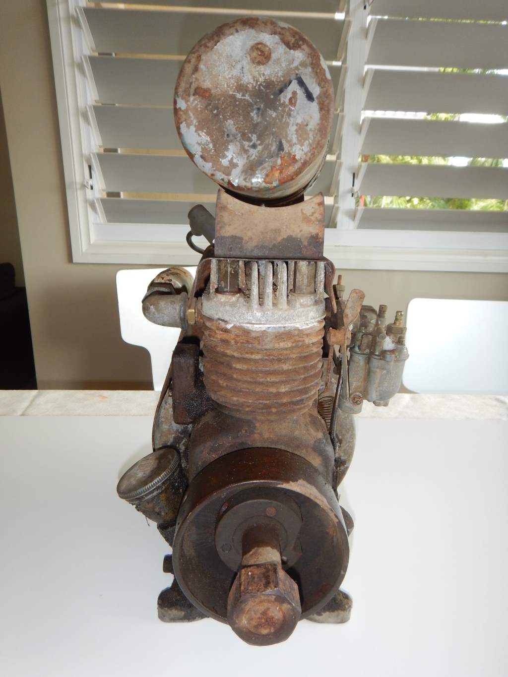
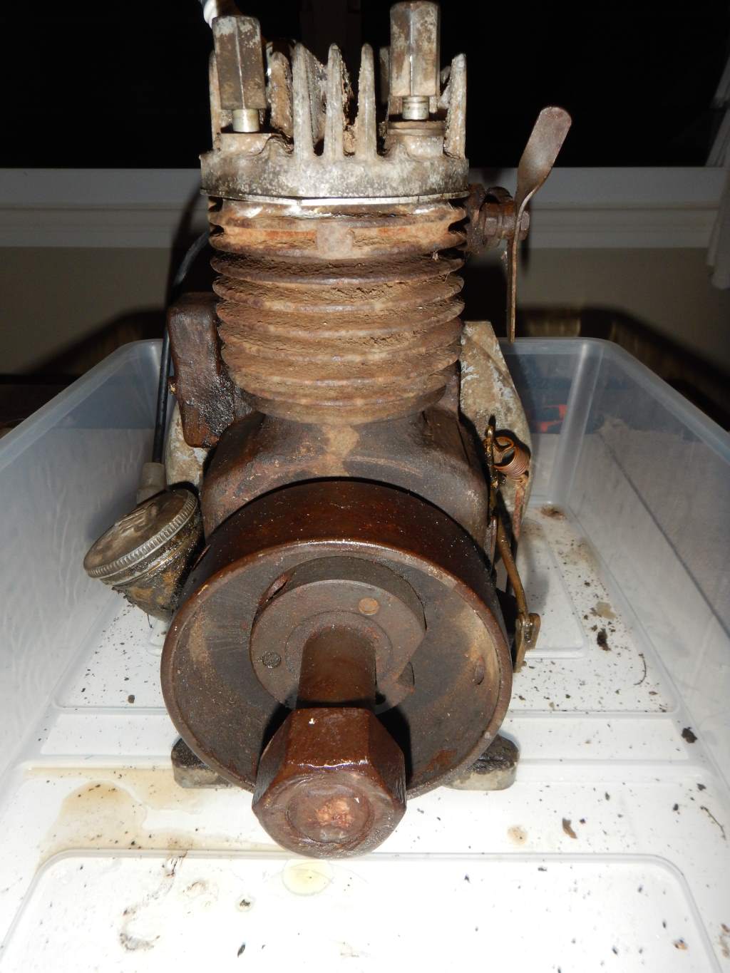
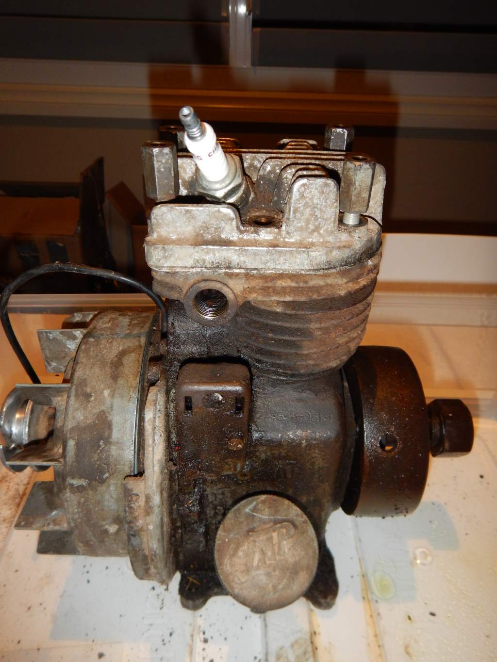
Really hit a hurdle at this stage - I was ready to get the crank out - but wasn't able to do it because of that chunky pulley you can see attached to it at the back of the engine.
It had to come off before I could pull the crank out - you couldn't push it out through the back of the engine - because the hole was only tiny - si it had to come out throught the front, but of course the pulley prevented that from happening as well.
Trouble is I just couldn't figure out how to get it off - it was stuck tight!! Posted to heaps of forums, got heaps of advice, but no-one could really give any definitive method of getting it off - it had a couple of holes that seemed to be there for a purpose - I thought they must be the key to getting it off - but no matter how I tried - it wasn't coming.
This picture shows what I'm trying to describe.
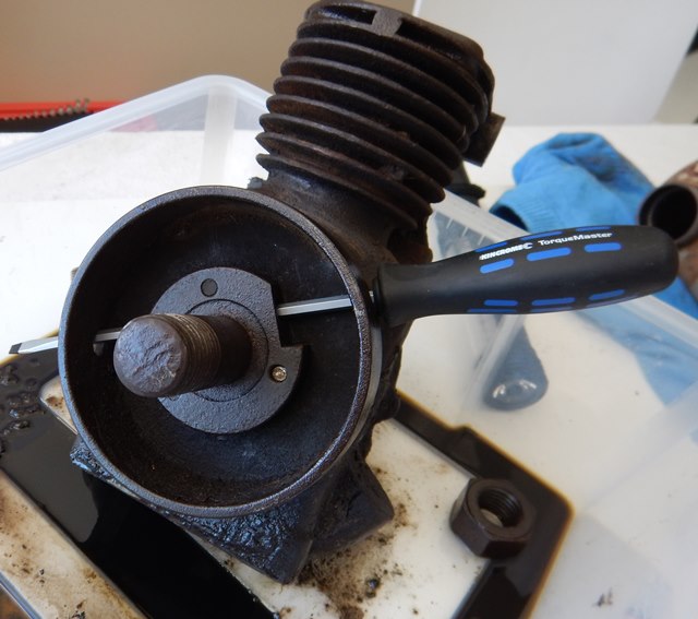
Some of the suggestions I got was just to in in behind it and bash it off using a big hammer - I was a bit nervous about doing that - I was worried that there might be some thread or something that I would strip by just bashing away at it. Anyway - suffice to say I tried everything I could think of short of a brute force attack - and no joy - so I packed it up and headed for Gran'ts place - (the local engine expert) - I prostrated byself at his feet begging for help. So he took pity on me and HE bashed it off the eng of the pulley with a whoppong great hammer and a couple of cold chisels - but it had us going for a while - it took some serious violence to get i8t off.
But of course as they say in all good Sci Fi s "Resistance is Futile!!" and eventually, after bashing away - we were rewarded with a great "crack" sound (Yes - I panicked!!) which was not the metal snapping, it was just the pulley finally breaking its bond on the crankshaft - and then with renewed vigor we eased the pulley off with the "delicate" use of a couple of 5lb hammers.
Once that was out - it was simple to pull out the crank - the timing gears - valves etc.
Then everything got a good degreasing and into Grant's industrial strength Ultrasonic cleaner. Came out really well too - so home I went with the engine completely disassembled.
That little episode with the pulley took me about a month and a half to resolve!!! and I really was stuck this time - just couldn't go on until the crank was out.....but there is a solution to every problem and unusually for me - this solution did not involve breaking more things than I fix.
So......here we have it....
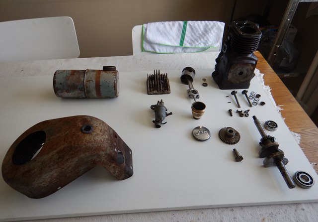
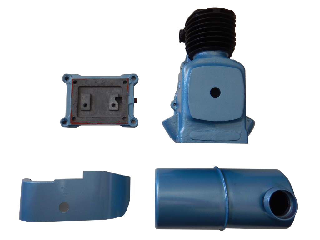
2 August 2015
So now the disassembly is done - the work commences to clean it up, restore it part by part, and the enjoyable part of getting it back together.
The colour is as close as I could find to the original J.A.P. Colour I could find. There were a number of spots where I could see the original colour of the engine - and I used those to gauge the colour and this is pretty close. It's called Polaris Blue, and its a Dupli-Colour spray can. I'm pretty happy with the way it came up too. The number one rule of any repainting is Preparation - Preparation - Preparation - and given that I didn't do an enormous amount of prep - I think it has come up pretty well. I think I could have made a much nicer job of the petrol tank if I had done a few reps of Sanding and paining to smooth things out - and fix the little imperfections. In fact I will probably go back and do it later. And once I was happy with the Blue - I then gave it a few coats of clear, and that set it off well. And again - if I had done any buffing it would have come up a lot better.
7 November 2015
As you can probably tell from the dates - I haven't down much to the little J.A.P. for some time now. The disassembly is done - I've started cleaning up and painting and had things ready to go back together but the trouble is one of the first things I had to do was put in the new bearings. I've never done this before so I've been a bit nervous. These things are an interferance fit, so they don't just push in nice and easy - I think the correct way of doing it is with a nice big press, but of course I don't have a nice big press. I thought about taking it down to a local mechanic to see if he'd do it for me - but that's not really in the spirit of doing a restoration myself. My first thought (as it always is) is to just bash it in with a whopping great hammer. I've taken this approach often enough in the past on other jobs to know that it results in more broken bits than it does restored bits. So.....what to do??
You Tube - That's what - you can learn to break anything on You Tube.
The thing with You Tube is you can't accept anything you see as gospel. What you should do - or at least what I do - is look around at everything you can find on your topic of interest and then pick out the one you are most comfortable with and see how you go.
And this is the one I came up with that made most sense to me.....
And there you have it - an easy way to fit your crank bearing with no tools!!
That makes a lot of sense to me - Physics - can't go wrong really - Ice will contract bearings - Heat will expand cases - simple.
But was it that simple in practice??
Yep!! You bet it was - the hardest part was driving down to Cairns to get a kilogram of Dry Ice (which cost $7). But once I had the dry ice - I just wrapped the bearings in a plastic bag and chucked them in an Eskuy with the dry ice.
In fact it was probably even easier than it looked in the video. For one side of the crank I heated the case and the bearing just slipped in by hand. For the other side - I didn't even heat the case - I just got the bearing out of the dry ice put it in the crank and gave it a tap with my fist, and in it went - perfect - I'm really happy with the way it went.
According to the J.A.P. Engine Guide, to dismantle the J.A.P. 2A you.....
- Disconnect high tension cable from spark plug
- Remove spark plug
- Remove Petrol pipe
- Remove Petrol Tank, complete with brackets and straps
- Remove Cowl, drawing high tension cable through rubbergrommet
- Remove Breather Box and Baffle
- Remove Magneto flywheel, using special extractor supplied for this purpose
- Remove High Tension Cable Clip
- Remove Cylinder Head and Valve Box Cover
- Remove Maqgneto and felt sealing ring, first disconnecting the cut-out wire
- Remove Aluminium Bearing Plate (6 nuts)
- Disconnect governor control spring, remove throttle link and throttle lever from carburetor, and from external end of governor rod
- Unscrew carburetor from inlet pipe
- Remove Governor Rod Bush from crankcase
- Remove Camwhjeel bolt, camwheel, cam lever bolt and cam levers
- Remove Pinion, with special extractor supplied for this purpose, together with the governor weight rings
- Remove Governor Sleeve and sSpring
- Remove Engine Base with Oil Trough
- Remove Split Pins from Big End bolts of connecting rod
- Remove Nuts and Big End Cap from Conrod
- Remove Conrod and Piston complete by drawing upwards through cylinder
- Remove Rings from Piston, one circlip and gudgeon pin
- Compress Valve Springs with Collars and remove cotters
- Remove Crankshaft from Engine
And to Re-Assemble the Engine - "Reverse the above procedure".
So I'd best be getting on with it.
10 November 2015
I don't really know too much about the history of this engine, but by looking at it, it seems to have been neglected for many years. So I decided to grind the valves and hone the bore - the bore actually looked quite OK, but I've never honed a bore before so I figured "Why not?"
20 May 2019
Yes - you read that right - it is now 3 1/2 year later - and I have just started putting the little J.A.P. back together!!!
I have moved house twice since my last update - and moved from Port Douglas south about 4,000 kilometers, and from there moved back North East about 12 hours back to Sydney - and although I am well and truely a country boy now - and don't like being back in the city - it is such a joy to be back with my tools and workshop - hence the revival of the J.A.P. 2a project.
As mentioned above, the first step is to replace the Crankshaft - a libral amount of Penrite Assembly Lube was used to coat the crank, and especially the journals.
Same goes for the valves and valve springs and valve guides - I really don't want the little fella starting up with no lube.
6 June 2019
I'm already beginning to learn a lot - mainly from things I "should" have done , but they are all noted and will definitely occur next time. Things like taking photos and videos of things before, during and after the disassembly. I mean, I did take photos and things, but not nearly enough. These days with digital cameras and videos there is really no reason not to take hundreds of the things. I found myself thinking, Öh yeah, that obviously goes on there", but 3 years later, things are not quite so obvious!!
A scrupulously clean workbench should go without saying, but it doesn't - I really should have been a lot cleaner for the rebuild process. Next time I will clean off the bench and then cover it with clean platic, or white paper or similar, you can't be too clean when reassembling an engine.
Today I got the crank in, along with the piston, and valve gear. The only slightly tricky part was getting the valve gear timed right - and its not tht tricky - there are two arrows to be lined upm one on the crank and one on the valve gear - You can see them marked on the photo below.
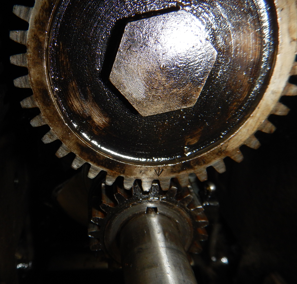
So just make sure the arrow on the crak cog lines up with the arrow on the cam gear, and you are good to go - easy.
So got the main internals back together and timed correctly - that's enough for today.
21 August 2019
Time to get the sump closed up. Simple matter of bolting on the bottom plate and then bolting on the Magneto backing plate.
Then things started to come just a little bit undone.
Once I got the magneto backing plate back on I put on the coil, points etc, all of the ignition system and I couldn't help myself, I had to see if it would spark. On with the flywheel and pull....nothing.....bummer. But I had read everywhere that these were very reliable magnetos and rarely failed, so I had some hope. I was thinking that the original owner had turfed it out simply because he didn't want to buy a new coil/magneto. But as I said, I still had hope.
I gave the points a bit of a clean (they were pretty grubby) with some Wet & Dry sandpaper and then flushed them with electrical contact cleaner and gave them some time to dry. Flywheel back on and pull.......NICE BIG FAT SPARK!!!! Huzzaaahh!
I was all enthused now - so I decided to put in a new set of points (dunno why, the existing ones seemed to be working fine). Took the old ones off, new ones one - nothing, no spark, nothing at all. BUGGER!
Anyway - after pfaffing around for months - yes months - I finally found an old photo of the JAP 2 ignition and tried to copy that. And it worked! The trouble I had was that the new points I installed seemed to be set up opposite to the points I took off, and I was trying to set up the new ones the same as the old ones, and it just wouldn't work. On the old ones, the fixed arm of the points was grounded, and one the new one, it was the moving arm (or vice-versa, I can't remember). Anyway, once I found that picture of the set up, I noticed it was the opposite of what my old points were set up like, so I followed that and bingo! I can't tell you the relief I felt when I saw the spark!
So it was a quick job to put the head back on so I was at the point where I could test it.
So the big moment - spray starter fluid into the spark plug hole, spark plug back in and pull - did it start first pull?? Nahhhh...but 3rd pull she fired up and ran for a second or two and then stopped - obviously as the starting fluid ran out. But that was great news. It must have been the first time that little engine fired in many, many years. It had cob-webs and spiders living all through it, even in the cylinder.
14 February 2020
Carby cleaning time - pull the whole thing apart, into hot soapy water, give it a scrub with a platic scrubbing brush and then to soak in Carby Cleaning fluid for a few hours.
Then blow it out with compressed air. So far it all looks pretty good, except the slow running jet seems to have been a bit chewed up in the past when someone either tightened it down too hard, or fought to get it out. Its a brass jet with a flat blade screw driver slot, and the head is a bit chewed up, but it should still be serviceable - it's not like I will have to get it in and out a lot.
Now into the ultrasonic cleaner for 20 minutes - and another blow out with compressed air. And all done.
Reassemble with new gaskets and a bit of petrol resistant gasket sealer and it should be good to go.
So reattach the carby to the engine, and see how she goes.
Of course I then couldn't resist the urge to get it running. So initially, just hooked it up to an external fuel tank to see how she'd go.
Here's a couple of videos to see how my early trials went. The results were pretty good, but I wasn't sure how to adjust the carby for best running.
There are only two adjustment screws, air and fuel. So I did a bit of research, and started off with what seemed like a good, generic setting to get the thing started.
My intial setting was:
- Fuel - Two full turns out
- Air - Two and a half turns out
And that seemed to be a good starting point - see for yourself below. The first video shows it running on the above settings. That seemed quite good, if somehwat fast.
The second video shows it running after a bit of pfaffing around with the settings.
July 2020
So now that it was running, the only thing really left to do was getting it running off its own fuel tank.
I needed to clean and paint the tank supports, which was pretty straightforward, and then attach them and the tank to the engine. I used a couple of Hose Clamps to secure the tank (which reminds me, I need to trim those). I got the fuel tap back on along with some clear fuel hose and an in-line fuel filter. and she's DONE!!!
The big moment is nigh.....
How did she go? See for yourself in the video below.
All that I need to do now is give it a good long run to let everything bed in, and build a nice stand for it.
Quite nice, and runs well for a 71 year old engine.